大雑把訳ポリキューブマップ
~ Translation : PolyCube-Maps ~
興味深かったので、実装しようかなぁとおもって適当に訳していたのですが、
時間がなくなってしまったので、実装できなかったので、これだけでも公開。
適当に訳したので、ひどい日本語や誤訳がややあると思いますが、勘弁してください。
PolyCube-Maps
ポリキューブ(立方体の面結合で出来る立体)を使ったテクスチャマッピング
Marco Tarini, Kai Hormann, Paolo Cignoni, Claudio Montani. Visual Computing Lab, ISTI / CNR, Pisa.
PolyCube-Maps - homepages
論文 Abstract 日本語訳
実際に取り扱うことになるメッシュに対する標準的なテクスチャマッピングでは、過度のひずみを回避し、メッシュのトポロジーをテクスチャの一部分と互換性をもつようにするために導入される、どうしても必要な継ぎ目の存在に苦しみます。 対照的に、キューブマップは、ひずみが少なく、継ぎ目のないのテクスチャ・マッピングのメカニズムを提供します。ただし、オブジェクトが荒い近似として立方体に似ている場合のみです。 私たちは、テクスチャの領域として、与えられたメッシュに関して、それに似ているポリキューブの表面を使用することにより、任意のメッシュへ、この概念を拡張します。 私たちの手法は、現在利用可能なグラフィックス・ハードウェアの範囲で実装するのが十分に簡単で、継ぎ目のないテクスチャ・マッピングの方法に結びつきます。
Standard texture mapping of real-world meshes suffers from the presence of seams that need to be introduced in order to avoid excessive distortions and to make the topology of the mesh compatible to the one of the texture domain. In contrast, cube maps provide a mechanism that could be used for seamless texture mapping with low distortion, but only if the object roughly resembles a cube. We extend this concept to arbitrary meshes by using as texture domain the surface of a polycube whose shape is similar to that of the given mesh. Our approach leads to a seamless texture mapping method that is simple enough to be implemented in currently available graphics hardware. that we tend to forget that they are a most limiting factor. In fact, it is well-known that seams cause: . Mesh dependence: The different levels-of-detail (LOD) of a multi-resolution model usually require an individual parameterization and texture image, unless care is taken that the patch boundaries coincide for all levels. . Inadequate filtering: Mip-mapping and bilinear interpolation both require the texels to be contiguous, a property that is not satisfied at the patch boundaries. As a consequence seams are
1 導入 Introduction
画像の色情報、あるいはそのほかの2Dの領域をもったいくつかの情報を使って3D物体の表面をテクスチャマッピングすることは、コンピューター・グラフィックス中の多くのアプリケーションには有用な方法です。その品質は、根本的にパラメター化の質に極度に依存します。 理想的には、パラメータ化は等角であるべきですし、どんな情報のゆがみも回避するために面積保存しているべきです。しかし、円錐や円柱のような展開可能な曲面のためにのみそのような理想的な写像が存在することがよく知られています。
The task of texture mapping a 3D surface with colour information from an image or with some other signal from a 2D domain is relevant for many applications in computer graphics and the quality of the result depends heavily on the quality of the underlying parameterization. Ideally, the parameterization should be conformal and area-preserving so as to avoid any signal distortion, but it is wellknown that such an isometric mapping exists only for developable surfaces like cones and cylinders.
したがって、三角形メッシュのための標準のアプローチは、低いひずみとなるように各々をパラメター化するいくつかの円盤状のパッチに表面を切ることです。この多重図表(multi-chart)あるいは地図(atlas)アプローチは必然的に継ぎ目を生みます。言い換えれば、3次元的に同じ位置座標値を持っているけれども、2次元的に異なるテクスチャ座標値があるような頂点をパッチの境界で複製する必要があります。
The standard approach for triangle meshes therefore is to cut the surface into several disk-like patches each of which can be parameterized with low distortion. This multi-chart or atlas approach inevitably produces seams, in other words, the boundaries of the patches need to be replicated so that there will be vertices that have the same position in 3D but different texture coordinates in 2D.
全体を包み込むよいマッピングを作成する工程は、与えられたメッシュを継ぎ目が最も目に見えなくなるように分割する問題に加えて、2Dの領域に適切な境界を定義し、個々のパッチのパラメター化を計算し、最後に長方形の形に効率的にテクスチャパッチを詰めることを要求します。 自動、半自動のアルゴリズムと同様に、細心の注意払ってモデルのuv-マッピングを手でつけているデザイナーも、これらの過程について最良となる可能な解答を見つけるために努力しています。また、私たちは非常に複雑なメッシュでさえ非常に良好な結果を与えるものを過去に発見しました。
Besides the problem of segmenting a given mesh such that the seams become least visible, the process of creating a good overall mapping also requires to define suitable boundaries of the charts in the 2D domain, to compute the parameterizations for each individual patch, and to finally pack the texture patches efficiently into a rectangular shape. Artists who manually design u-v-mappings of their models with great care, as well as automatic or semi-automatic algorithms, strive to find the best possible solution for each of these steps and we have seen extremely good results even for very complex meshes in the past.
しかしながら、私たちは、「三角形メッシュのテクスチャ・マッピングは区分化を要求する」という格言、および継ぎ目が存在することに慣れていて、それらは最も取り除くべき要因であることを忘れる傾向があります。実際、継ぎ目は次のようなことをもたらすことが有名です:
・メッシュ依存性:多重詳細度に対応したモデルでは、パッチ境界が全てのLODレベルで一致するように注意するなら話は別ですが 、通常、異なるLODメッシュに対しては別々のパラメター化およびテクスチャイメージを要求します。
・不適当なフィルタリング:ミップマップおよびバイリニア補間は、両方とも、テクセルが連続していることを要求します。これらの条件は、パッチ境界では満たされません。結果として、継ぎ目が目に見えます。
・テクスチャメモリの浪費:最良の詰め込みアルゴリズムでさえ、いくつかのテクスチャ領域がテクスチャパッチによって覆われないことを避けられません。覆われていないテクセルは、部分的には境界部分を広げて幾らかのテクセルを加えることにより、上で言及されたフィルタリングの不適当な部分を防ぐために使われるでしょう。しかし、一般には、覆われない部分は情報を格納せず、浪費されていると考えなければいけません。
However, we are so used to the maxim that texture mapping of
triangle meshes requires a segmentation and the existence of seams,
that we tend to forget that they are a most limiting factor. In fact, it
is well-known that seams cause:
・ Mesh dependence: The different levels-of-detail (LOD) of a
multi-resolution model usually require an individual parameterization
and texture image, unless care is taken that the patch
boundaries coincide for all levels.
・ Inadequate filtering: Mip-mapping and bilinear interpolation
both require the texels to be contiguous, a property that is not
satisfied at the patch boundaries. As a consequence seams are
visible.
・Wasted texture memory: Even the best packing algorithms
cannot avoid that some parts of the texture domain are not
covered by a texture patch. The uncovered texels may be used
to partially prevent the filtering artefact mentioned above by
adding a certain number of texels to enlarge the chart boundaries,
but in general they do not store any information and
must be considered wasted.
この論文では、私たちは、最初の2つの欠点を回避し、テクスチャメモリをほとんど浪費しない優秀なテクスチャ・マッピング用の新しいメカニズムであるポリキューブマップ(PolyCube-Map)を導入します。それは、有名なキューブマップメカニズムの一般化と見なすことができます(セクション2を見よ)。
In this paper we introduce PolyCube-Maps, a new mechanism for superior texture mapping, that avoids the first two drawbacks and wastes almost no texture memory. It can be seen as a generalization of the well known cube map mechanism (see Section 2).
1.1 関連した業績 Related work
テクスチャ・マッピングのほとんどの研究は、よい地図の生成、すなわち分割、パラメター化および詰め込みに関して、異った見地から見た様相で焦点が変化する多重図表アプローチを追求します。
Most of the work on texture mapping follows the multi-chart approach with varying focuses on the different aspects of a good atlas generation, namely partitioning, parameterization, and packing.
ひずみのないパラメター化を可能にするために、[Cignoni et al. 1999]および[Carr and Hart 2002]は、単一の三角形あるいはペアの三角形からパッチを構成することを提唱しました。しかし、これは高度に断片化されたテクスチャ空間に帰着し、メッシュの至る所で継ぎ目が発生します。 他のアプローチはより大きなパッチを考慮し、それぞれのパッチを可能な限り等角か面積保存するものとしてパラメター化しようとしました[Maillot et al. 1993; L´evy et al. 2002; Grimm 2002; Sorkine et al. 2002; Sander et al. 2003]。 パラメター化についてのもっと詳述な情報について興味を持った読者には、[Floater and Hormann 2004]による最近の調査を参照してください。
In order to enable parameterizations without any distortion, Cignoni et al. [1999] and Carr and Hart [2002] propose to let the patches be composed of a single triangle or pairs of triangles, but this results in a highly fragmented texture space and introduces seams all over the mesh. Other approaches consider larger patches and try to make the parameterization per patch as conformal or areapreserving as possible [Maillot et al. 1993; L´evy et al. 2002; Grimm 2002; Sorkine et al. 2002; Sander et al. 2003]. For more detailed information on parameterizations in general we refer the interested reader to the recent survey by Floater and Hormann [2004].
多重図表方法は、上で言及したすべての欠点を備えた継ぎ目を生むという事実に苦しみます。 したがって、幾人かの研究者[Piponi and Borshukov 2000; L´evy et al. 2002; Sheffer and Hart 2002]は、継ぎ目が最も目に見えない表面のきり方を提案しました。 さらにいえば、三角形はパッチ境界を横断することを許されないので、継ぎ目は、根本的にメッシュの幾何学的な表現を極度に抑制します。 例えば、1つのテクスチャが多重詳細度モデルのすべてのLODに対して使用される場合には、これは厳しい制限です。 [Cohen et al. 1998]は、パッチ境界を適切に扱うことができる制限付きの単純化されたシーケンスを備えた多重詳細度モデルの構築により、この問題に取り組みました。また、この方法は[Praun et al. 2000]によって改良されました。
Multi-chart methods suffer from the fact that they produce seams with all the drawbacks mentioned above. Several authors therefore suggested to cut the surface where the seam is least visible [Piponi and Borshukov 2000; L´evy et al. 2002; Sheffer and Hart 2002]. Moreover, seams heavily constrain the underlying geometric representation of the mesh because triangles are not allowed to cross the patch boundaries. This is a severe limitation, for example, if one single texture shall be used for all LODs of a multi-resolution model. Cohen et al. [1998] addressed this problem by constructing the multi-resolution model with a constrained simplification sequence that handles the patch boundaries appropriately and an improvement of this method was presented by Praun et al. [2000].
継ぎ目を持つことを回避するただ一つの方法は、与えられたメッシュと同じトポロジーを持ち似たような形を持つテクスチャ領域を選ぶことです。 三角形にあらかじめ分割されたメッシュに関して継ぎ目の無いパラメター化の構築をし[Eck et al. 1995; Lee et al. 1998; Khodakovsky et al. 2003; Praun and Hoppe 2003]、再メッシュ化およびメッシュ圧縮に使用しているいくつかの方法がすでに存在しています。
The only way to avoid having seams is to choose a texture domain that has both the same topology as the given mesh and a similar shape. There exist several methods that construct a seamless parameterization of a mesh over a triangulated base complex [Eck et al. 1995; Lee et al. 1998; Khodakovsky et al. 2003; Praun and Hoppe 2003] and use it for remeshing and mesh compression.
1.2 あらまし Overview
これらの継ぎ目の無いのパラメター化の方法をテクスチャ・マッピングのために使用することができるかもしれません。 基礎的な複雑さとなる三角形の領域上で色情報を定義することができるかもしれないし、メッシュ三角形に色を直線的に射影する目的で、メッシュ頂点のパラメーター値を使用することができるかもしれません。 しかしながら、メッシュの三角形の頂点が異なる領域の基礎三角形にパラメーター値を持っており、それらの補間が色情報が定義された表面の外にある分割三角形の場合、障害が発生します。
In principle, these seamless parameterization methods could also be used for texture mapping. Colour information could be defined on the domain triangles of the base complex and the parameter values of the mesh vertices could be used to linearly map the colour to the mesh triangles. However, difficulties arise when the vertices of a mesh triangle have parameter values on different domain triangles and their linear interpolation is a secant triangle that falls outside the surface on which the colour information is defined.
私たちのアプローチはちょうどスケッチするようなものです。しかし、基礎的な複雑さとなる三角形を使用するのではなく、テクスチャ領域としてポリキューブの表面を使用します。 この表面の特別の構造は、標準の2Dテクスチャの色情報を効率的に格納しアクセスすることを可能にするだけでなく、テクスチャ領域に単にそれらを投影することにより正割三角形の問題を扱うことができます。 現在利用可能なグラフィックス・ハードウェアの上で、この射影および色アクセスの両方をインプリメントすることは十分簡単です。 その結果、私たちは新しい継ぎ目の無いテクスチャ・マッピング技術を持ちます。 ここでは、キューブマップの概念から派生した、ポリキューブマップの背景にある基礎的な考えについての説明からスタートしましょう。
Our approach is similar to the idea that we just sketched, but instead of using a triangulated base complex we use the surface of a polycube as texture domain. The special structure of this surface not only allows to efficiently store and access the colour information in a standard 2D texture, but also to handle the problem of secant triangles by simply projecting them onto the texture domain. Both this projection and the colour access are simple enough to be implemented in currently available graphics hardware. As a result we have a new seamless texture mapping technique. But let us start by explaining the basic idea behind our PolyCube-Maps which stems from the concept of cube maps.
2 ポリキューブマップ PolyCube-Maps
キューブマップは、一般に環境マップに使用されます、しかし、それらはりんごのようなものに関して、継ぎ目の無いテクスチャ・マッピングを定義するために使用するできます(図1を参照)。 実際、私たちがする必要のあるのは、そのような3Dモデルの各頂点に3Dテクスチャ座標値(それは頂点位置と異なることができる)を設定することです。 私たちは、テクスチャ座標値を定義することが可能な空間を3Dテクスチャ空間と呼び、頂点位置を保存するオブジェクト・スペースR3と区別するためにT3で表記します。 キューブマップのメカニズムでは、原点に中心を備えた単一の立方体の表面にすべてのフラグメントのテクスチャ座標値を投影するために単純な中央からの射影を使用するでしょう。 この立方体の表面を3Dテクスチャ領域と呼び、T3⊂T3となるT3によってそれを表記しましょう。 キューブマップのメカニズムでは、T3上の各点をキューブの各面と対応させた6枚の4角形テクスチャ画像である2次元のテクスチャ空間上の点に対応させるでしょう。 私たちは、この2Dテクスチャ領域をT2と記述します。 最終的なマッピングからは継ぎ目が消え、私たちがイントロダクションで指摘した欠点をすべて回避するでしょう。 しかしながら、キューブマッピングは、球体に似た形のときにだけ動作するという点で、かなりまれにしか使えません。
Cube maps are commonly used for environment mapping, but they can also be used to define a seamless texture mapping for, say, an apple (see Figure 1). In fact, all we need to do is to assign to each vertex of such a 3D model a 3D texture position (which can differ from the vertex position). We call the space of possible texture positions the 3D texture space and denote it by T3 to distinguish it from the object space R3 that contains the vertex positions. The cube map mechanism will then use a simple central projection to project the texture position of every rendered fragment onto the surface of a unitary cube with its centre at the origin. Let us call the surface of this cube the 3D texture domain and denote it by T3 with T3 ⊂ T3. The cube map mechanism will further associate each point of T3 with a position in a 2D texture space, which in this case is a collection of six planar square texture images, one for each face of the cube. We denote this 2D texture domain by T2. The resulting mapping will be seamless and will avoid all the drawbacks that we sketched in the introduction. However, this use of cube maps is fairly uncommon because it works only for quasi-spheres and our main idea is to extend this concept to more general shapes.
ポリキューブマップでは、3Dテクスチャ領域T3として単一の立方体ではなくポリキューブの表面を使用します。 ポリキューブは、向かいあった面の軸をそろえてくっつけた単位立方体から構成された形です(図2(左)を参照)。 使用されたポリキューブは、最良の結果を得るために、非常に荒く近似したメッシュの形に似ているべきであり、大まかな特徴を捕らえているべきです。
For our PolyCube-Maps we use as 3D texture domain T3 the surface of a polycube rather than a single cube. A polycube is a shape composed of axis-aligned unit cubes that are attached face to face (see Figure 2, left). In order to get the best results, the used polycube should very roughly resemble the shape of the given mesh and capture the large scale features.
一旦ポリキューブが定義されれば、私たちは以下のように進みます。
最初に、私たちはメッシュの各頂点vにユニークな3Dテクスチャ座標値
vT3 = (vr,vs,vt ) ∈ T3.
を設定します。
レンダリング時には、頂点およびそれらの3Dテクスチャ位置がグラフィックス・パイプラインに供給されます。また、ラスタライザーは、生成された全てのフラグメントfに関して3Dテクスチャ座標値 fI3 を得るために、3D座標を補間してフラグメントシェーダへ受け渡します。
すべての3Dテクスチャ座標値 vT3 がT3の上に横たわっていたとても、これは必ずしも補間された3Dテクスチャ座標値 fI3 がT3上にあるとは限りません。
したがって、フラグメントシェーダは fI3 を 3Dテクスチャ領域のポイントfT3へマッピングするために射影P:T3→T3を適用します。
さらに、フラグメントシェーダは、2Dテクスチャ領域T2に格納されるfT3を使って色情報を決定する別の写像M:T3→T2を施します(2Dにして考えた場合の例は、図3を参照)。
ここででは、T2はいくつかの正方形パッチを詰め合わせた1つの単一の長方形のテクスチャイメージです。
Once the polycube is defined, we proceed as follows.
First we assign to each vertex v of the mesh a unique 3D texture position
vT3 = (vr,vs,vt ) ∈ T3.
At rendering time, the vertices and their 3D texture positions are fed to the graphics pipeline and the rasterizer interpolates the latter ones to get a 3D texture position fI3 for every produced fragment f and passes it on to the fragment shader.
Even if all 3D texture positions vT3 lie on T3, this is not necessarily the case for the interpolated 3D texture position fI3.
Therefore, the fragment shader applies a projection P : T3 → T3 to map fI3 to a point fT3 in the 3D texture domain.
It further uses a second mapping M : T3 → T2 to determine the colour information at fT3 that is stored in the 2D texture domain T2 (see Figure 3 for the 2D analogue).
In our case, T2 is one single rectangular texture image with a packing of several square patches.
ポリキューブマップの中で最も重要な特徴は、たとえテクスチャ情報がそれ自身正方形イメージの集まりとして構成されていても、オブジェクトの表面で3Dテクスチャ座標が連続的に変わった時に、継ぎ目の無いのテクスチャ・マッピングを可能にするということです。
The most important feature of PolyCube-Maps is that the 3D texture coordinates vary continuously over the surface of the object and therefore enable a seamless texture mapping even though the texture information itself is stored as a collection of square images.
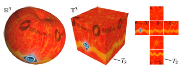 図1:キューブマップは、りんごに関して継ぎ目無くテクスチャマッピングできます(左)。この場合、3Dテクスチャ領域T3は3DテクスチャスペースT3に埋め込まれた、単一の立方体の表面で(中央)、6つの正方形の画像から成る2Dテクスチャ領域T2と一致します。(右)
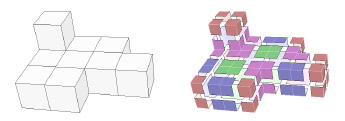 図2:10このキューブからなるポリキューブ(左)と、3節で説明される各表面のセルへの分割(右)。
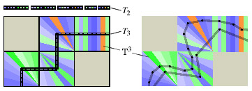 図3:我々の方法の2Dの場合:射影Pは3Dテクスチャ領域T3(左)上にT3の中で定義された各点(あるいはフラグメント)をマッピングします。
その後、マッピングMは、2Dテクスチャ領域T2からのテクスチャ情報を調べるために使用することができます。
ポリキューブマップは、異なるメッシュの構造と結び付けられていないので、異なるメッシュの表現を使うことができます(右)。
図3:我々の方法の2Dの場合:射影Pは3Dテクスチャ領域T3(左)上にT3の中で定義された各点(あるいはフラグメント)をマッピングします。
その後、マッピングMは、2Dテクスチャ領域T2からのテクスチャ情報を調べるために使用することができます。
ポリキューブマップは、異なるメッシュの構造と結び付けられていないので、異なるメッシュの表現を使うことができます(右)。
3 どのようにポリキューブマップが動作するか How PolyCube-Maps Work
私たちがどのように関数PおよびMを定義するか、今一度詳細に説明しましょう。 私たちがポリキューブマップををテクスチャ・マッピングとして使用したいと考えていて、PおよびMの両方が、グラフィックス・パイプラインのよりきついサブループであるフラグメントシェーダの中で計算されるべきであることを覚えておいてください。 したがって、それらのインプリメンテーションはできるだけ単純で迅速でなくてはなりません。 これを達成するために、私たちは、T3の上に区分的に両方の写像を定義します。
Let us now explain in detail how we define the functions P and M. Remember that we want to use PolyCube-Maps for the purpose of texture mapping and both P and M must be computed in the fragment shader which is the tighter sub-loop of the graphics pipeline. Therefore their implementation must be as simple and quick as possible. To achieve this, we define both mappings piecewise over an adequate partition of T3.
私たちは、ポリキューブが構成される立方体とサイズおよび方位が等しい、立方体のセルへ3Dテクスチャ空間T3を細分します。しかし、私たちは各方角へ0.5だけ、これらのセルを移動して、ポリキューブの頂点をセルの中心に位置するようにしました(2Dにして考えた場合の例は図4を参照)。
私たちは、次の利点のためにこの双対的な分割を選びました:
1. T3の点の位置をセル内に決定するのが容易で、
2. ポリキューブの表面と交差するセルに関する、異なる配置の数が、少数に制限されていて、
3. これらの配置の各々については、各セルにおいて関数PおよびMを区分的に定義し、それらをセルの面において連続的にすることが可能で、
4. これらの関数、PとMを計算することが簡単です。
We subdivide the 3D texture space T3 into cubic cells that are equal in size and orientation to the cubes that the polycube is composed of, but we offset these cells by 0.5 in each direction such that the vertices of the polycube lie at their centres (see Figure 4 for the 2D analogue).
We chose this dual partition because of the following advantages:
1. it is still easy to determine in which cell a point in T3 lies,
2. the number of different configurations that can occur in the cells which intersect with the surface of the polycube is limited to a small number,
3. for each of these configurations it is possible to define the functions P and M piecewise inside each cell and still make them continuous at the faces of the cells,
4. these functions P and M are simple to compute.
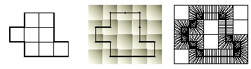 図4:別の2Dにして考えた場合:オブジェクトの表面をポリキューブで荒く近似し(左)、ポリキューブの角を中心にした単位立方体の双対空間を考え(中央)、最後に、個々の空でない立方体の内部の各点をポリキューブ表面に対応させる射影を所得します(右)。
3.1 セルの配置 Cell configurations
セルとポリキューブ表面T3の交差で、ポリキューブの顔を4つのフェイスレット(facelet)へ分割するものを考慮します。 ポリキューブによるセルの内部で起きうるフェイスレットの交差面の配置は、63の異なる場合があります。なお、我々は、2多様体の場合を取り扱います。 これらの配置は、回転と鏡像の類似性によって同じものを取り除けば、図5にある6つの基礎的な配置まで減らせます。 各セルは3~6個のフェイスレットを含んでいます。 例えば、単一の立方体から成るポリキューブは、3つのフェイスレットを各々含んでいる8個のセルへ分解されます(図6を参照)。 色のコード化によって基礎的な配置を参照し、各セルの内部のフェイスレットが薄い白線によって区切られる、より複雑な例は図2および図11の中で示されます。
We now consider the intersection of the cells with the polycube surface T3 and remark that it naturally subdivides the faces of the polycube into four facelets. There are 63 different configurations of facelets that can occur inside a cell which intersects with the polycube since we only consider polycubes with a two-manifold surface. These configurations can be further reduced down to the six basic configurations in Figure 5 if we take out rotational and reflectional similarities. Each cell contains between three and six facelets. For example, the polycube that consists of a single cube is decomposed into eight cells containing three facelets each (see Figure 6). More complex examples are shown in Figures 2 and 11 where the colour coding refers to the basic configuration and the facelets inside each cell are separated by thin white lines.
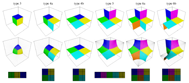 図5:空でないセルにおける(回転と鏡像を取り除いた)6つの基礎的な配置。
トップです:個々のフェイスレットのための異なる色を備えたセルの内部のポリキューブの表面のT3のサブ一部。
中心:セルの内部におけるPの投影線;それらは角表面と直交します。
底:パッチの中へのスクエアレット(squarelet)の詰め込み;スクエアレットの色は関連するフェイスレットの色に相当します。
図5:空でないセルにおける(回転と鏡像を取り除いた)6つの基礎的な配置。
トップです:個々のフェイスレットのための異なる色を備えたセルの内部のポリキューブの表面のT3のサブ一部。
中心:セルの内部におけるPの投影線;それらは角表面と直交します。
底:パッチの中へのスクエアレット(squarelet)の詰め込み;スクエアレットの色は関連するフェイスレットの色に相当します。
3.2 射影 P The projection P
基礎的な配置の各々については、セルの内部でどんなポイントvT3=(vr、vs、vt)に対しても射影方向を指定することにより、T3の上にT3の中のポイントを射影するprojection P を定義することができます。一般性を失うことなく、座標の範囲を(0、0、0)から(1、1、1)とすると、最初の4つの配置は次で与えられます。
| type3 | (r、s、t) |
| type4a | (r、0、t) |
| type4b | (0、0、1) |
| type5 | (r/s-r, 1-s, 1-t) (s>=r) |
| (1-r, s/r-s, 1-t) (s< r) |
For each of the basic configurations we can now define the projectionP that maps points in T3 onto T3 by specifying the projection direction at any point vT3 = (vr,vs,vt ) inside the cell. If we assume without loss of generality that the coordinates are between (0,0,0)and (1,1,1) then the projection direction of vT3 for the first four configurations is given by type3:(r、s、t), type4a:(r、0、t), type4b:(0、0、1), type5:(r/s-r, 1-s, 1-t) (s>=r),(1-r, s/r-s, 1-t) (s< r), The formulas for the other two cases are slightly more complicated but since we did not use them in our implementation (see Section 5.2) we omit them for the sake of brevity.
そのように定義された射影のよい特性は、無限に多数の交差しないラインでそれらがセルの内部を分割するということです。すなわち、ラインの上のポイントがすべてT3上の同じポイントに投影されます。 更に、T3上の2個の近隣のセルの射影ラインは共通の面の上にあるので、射影は全体的に連続的です。 図5の中の中央の列は、6つの基礎的な配置のための射影がどのように見えるかを表現します。また、2Dにして考えた場合の例は図4の右側に示されます。
A nice property of the so-defined projections is that they partition the interior of the cell into (infinitely many) non-intersecting lines such that all points on each of these lines are projected to the same point on T3. Furthermore, the projection lines of two neighbouring cells are identical on the common face and hence the projection is globally continuous. The central row in Figure 5 gives an idea how the projections for the six basic configurations look like and an example of the 2D analogue is shown on the right of Figure 4.
 図6:図1のりんごモデル用の単純なポリキューブマップの例。
ポリキューブは異なる回転をすると、タイプ3の8個のセルへ、細分化されます。
各セルは、1セットの3のテクスチャスクエアレットとして格納される3つのフェイスレットを含んでいます。
図6:図1のりんごモデル用の単純なポリキューブマップの例。
ポリキューブは異なる回転をすると、タイプ3の8個のセルへ、細分化されます。
各セルは、1セットの3のテクスチャスクエアレットとして格納される3つのフェイスレットを含んでいます。
3.3 マッピング M The mapping M
概念的に、私たちがテクスチャ・マッピングのために使用する色情報はすべて3Dテクスチャ領域T3、つまりポリキューブのフェイスレットの上で定義されます。 私たちは3Dテクスチャとして色情報を格納することができました。しかし、ほとんどのボクセルが空でしょうから、この選択は非常に不経済すぎます。 代わりに、私たちはキューブマップのものと似た技術を使用します。
Conceptually, all colour information that we use for texture mapping is defined on the 3D texture domain T3, i.e. on the facelets of the polycube. We could store the colour information as a 3D texture, but since most of the voxels would be empty, this option is by far too wasteful. Instead, we use a technique similar to the one that is used by cube maps.
T3の中の各フェイスレットは正方形の領域です。また、マッピングMは2Dテクスチャ領域T2の中の対応するスクエアレットにこの領域をマッピングします。 2の累乗とすべきサイズSがユーザー定義されたパラメーターとして、私たちのスクエアレットは S×S テクセルから成ります。
Each facelet in T3 is a square region and the mapping M maps this region to a corresponding squarelet in the 2D texture domain T2. Our squarelets consist of S×S texels where the size S is a userspecified parameter that must be chosen as a power of two.
1個のセルのフェイスレットのためのスクエアレットはすべて、図5の下の列の中で示されるような大きな長方形のテクスチャパッチの中に全てくっつけられます。 テクスチャパッチの形により、それらは容易にT2に詰めることができ、個々のセルのグローバルな2Dオフセットとして例えば上部の左コーナーの位置を蓄えることができます。 それらが6つの基礎的な配置の各々のために固定されるので、テクスチャパッチの内部の個々のスクエアレットへのローカルのオフセットを格納する必要がありません。
All the squarelets for the facelets in one cell are packed together in a larger rectangular texture patch as shown in the bottom row of Figure 5. Due to the shape of the texture patches, they can easily be packed into T2 and the position of, for example, the upper left corner can be stored as a global 2D offset for each particular cell. The local offsets to the individual squarelets inside the texture patch do not need to be stored as they are fixed for each of the six basic configurations.
したがって、セルの内部のポイントp∈T3に写像Mを適用する作業は、3ステップから成ります。 最初に、pの相対的な位置を決定し、対応するスクエアレットの中の相対的な位置を与えるためにSを掛けます。 その後、結果は、テクスチャパッチの内部のスクエアレットの固定詰め込み法によってオフセットされます。また、最後に、T2の中のそのパッチのグローバルオフセットが加えられます。
Thus, applying the mapping M to a point p ∈ T3 inside a cell consists of three steps. First, the relative position of p inside the containing facelet is determined and multiplied with S to give the relative position in the corresponding squarelet. Then the result is offset according to the fixed packing of the squarelets inside the texture patch and finally, the global offset of that patch in T2 is added.
ローカル、グローバルのオフセットは共にSの倍数です これは、後のミップマップレベルが同じスクエアレットら来るテクセルだけを合成し、各スクエアレットが最も粗いミップマップレベルlog2(S)の上で単一のピクセルによって表わされるということを意味します。
Both the local and the global offset are a multiple of S. This means that subsequent mip-map levels will merge together only texels coming from the same squarelet and that each squarelet is represented by a single pixel on the coarsest mip-map level log2(S).
4 3次元参照表(Look-up Table) The 3D Look-up Table
ポリキューブはテクスチャが張られたメッシュに対して適応されるに違いありません。したがって、私たちはポリキューブを指定するポリキューブマップを使うアプリケーションに対して柔軟な方法を提供することが必要になります。 私たちの解決は、3D参照テーブルT3LUTにT3のセル構造を格納し、T3LUTの対応するエントリーの中で1セットのパラメーターによって各セルを定義することです。 フラグメントシェーダがアクセスすることができるように、この参照テーブルはテクスチャメモリの中に置かれるに違いありません。 それは小さな3Dテクスチャとして格納することができます。もしくは、レンダリング時の状態変数の数を減らすために、一連の繋がったものと加工して、T2の一部分として物理的に保持することができます。
The polycube must be adapted to the shape of the mesh that is to be textured and therefore we need a flexible way for the application that uses PolyCube-Maps to specify the polycube. Our solution is to store the cell-structure of T3 in a 3D look-up table T3LUT and define each cell through a set of parameters in the corresponding entry of T3LUT . This look-up table must be kept in texture memory so that it can be accessed by the fragment shader. It can either be stored as a small 3D texture or, in order to reduce the number of rendering-time state variables, it can be serialized and physically kept in a subpart of T2.
フラグメントfを処理する場合、フラグメントシェーダは最初にフラグメントに関する補間された3Dテクスチャ座標値 fI3を含んでいるセルを決定します。 対応するフラグメント処理でのT3LUTへの1回のテクスチャアクセスで、最終的な2Dテクスチャ座標値fT2∈T2を決定するのに使われるPおよびMを計算するのに必要なパラメーターはすべて得られます。
When processing a fragment f , the fragment shader first determines the cell that contains the fragment’s interpolated 3D texture position fI3. A single texture access to T3LUT at the corresponding entry returns all the parameters needed to compute P and M which are then used to find the final 2D texture position fT2 ∈ T2.
T3LUTの各エントリーは、1つの(r、g、b)テクセルにまとめられます。その結果、一回のテクスチャに読み込み命令でそれを取って来ることができます。 より正確にいうと、エントリーeはC、RおよびOの3つの部分から構成されます:
- e.C は、6つの基礎的なセル配置のうちの1つのインデックスです。
- e.R は24の軸の回転のうちの1つのインデックスです。
- e.O はT2上にあるeに対応するパッチのグローバルオフセットです。
Each entry of T3LUT is packed in one (r,g,b)-texel, so that it can be fetched with a single texture read instruction. More precisely, an entry e is composed of three parts: C, R, and O, where e.C is the index of one of the six basic cell configurations, e.R is the index of one of the 24 axis-to-axis rotations, e.O is the global offset of the patch corresponding to e in T2. The rotation e.R maps each axis into another axis in the positive or negative direction and is used to transform the given cell into the default orientation of the configuration e.C shown in Figure 5. If there are several different rotations that achieve this, any of them can be chosen.
値e.Cおよびe.Rが単一のバイトにまとめられる一方、e.Oは各座標で2バイトを必要とします。 これらの座標はSの倍数で表現されるので、それらを格納するのに8ビットで十分です。 さらに、T3LUTをランダムアクセス・テーブルにするために、私たちはポリキューブのバウンディングボックスにある全ての空のセルを含みます。
While the values e.C and e.R are packed together in a single byte, e.O requires two bytes, one for each coordinate. These coordinates are expressed in multiples of S so that 8 bits are sufficient to store them. To make T3LUT a random access table, we also include all the empty cells in the bounding box of the polycube.
しかしながら、ポリキューブが典型的には少数の立方体だけから成るので、参照テーブルはまだ非常に小さい。 私たちがこの論文の中で示す例において、T3LUTは常に1キロテクセル未満です。しかし、最終のテクスチャT3は数メガテクセルでありえます。
However, the look-up table is still very small as a polycube typically consists of only a small number of cubes. In the examples that we show in this paper, T3LUT is always smaller than one Kilo texel, whereas the final texture T2 can be several Mega texels.
モデルがマルチテクスチャ(例えばカラーマップ、法線マップおよび反射係数マップ)の場合、テクスチャはすべて同じポリキューブマップを共有することができ、同じT3LUTによってそれらにアクセスすることができます。
If a model has multiple associated textures (e.g. a colour map, a normal map, and a specular coefficient map) then the textures can all share the same PolyCube-Map and they can be accessed through the same T3LUT .
5 フラグメントシェーダプログラム Fragment Shader Program
フラグメントシェーダへ入力される3Dテクスチャ座標値fI3∈T3を備えたフラグメントは、次の擬似コードによって記述されるフラグメントプログラムによって処理されるでしょう:
1. fI3 を含むセルの3Dインデックス値 i ∈ N3 をi = [ fI3 +(0.5,0.5,0.5)]によって決め、さらにセル内での位置fs = fI3-i を決定する。ここで、fs ∈ [0.5,+0.5)3。
2. インデックスiを使って、テクスチャT3LUTからエントリーeを取って来る。
3. fsの方位をe.Rで回転させて(セクション5.1を参照)、
4. 状態e.C(セクション5.2を参照)のために定義されるような、射影Pおよび(グローバルオフセットのない)マッピングMを適用して、
5. グローバルオフセットe.Oを加えて、
6. 2DテクスチャT2の中の最終的なテクセル値にアクセスするために、以上の結果をインデックスとして使用します(セクション5.3を参照)。
参照テーブルT3LUTが、2DテクスチャT2の小さな一部分に格納される場合、インデックスiは第2のステップの最初に変換しなくてはなりません。
更に、モデルが多数のテクスチャを持っている場合、最後のアクセスは同じテクスチャ座標を使います。
Each fragment that enters the fragment shader with a 3D texture position fI3 ∈ T3 will undergo the fragment program that is described by the following pseudo-code:
1. compute the 3D index i ∈ N3 of the cell that contains fI3 by i = [ fI3 +(0.5,0.5,0.5)] and the subcell position fs = fI3i with fs ∈ [0.5,+0.5)3,
2. fetch the entry e from the texture T3LUT at index i,
3. rotate fs around the origin by e.R (see Section 5.1),
4. apply the projection P and the mapping M (without the global offset) as defined for case e.C (see Section 5.2),
5. add the global offset e.O,
6. use the result as an index to access the final texel value in the 2D texture T2 (see Section 5.3).
Note that the index i must first be serialized in the second step if the look-up table T3LUT is kept in a tiny subpart of the 2D texture T2.
Furthermore, if a model has multiple associated textures, then the last access is repeated for each texture using the same coordinate.
空間の部分ボリュームに関する情報にアクセスするために3D参照テーブルを利用する、テクスチャに関する同様のアプローチは、ボリュームデータセットを圧縮する全く異なる情況の中で使用されました[Schneider and Westermann 2003]。
A similar texturing approach that utilizes a 3D look-up table in order to access information relative to a sub-volume of the space has also been used in the totally different context of compressing volumetric datasets [Schneider and Westermann 2003].
OpenGL ARB フラグメントプログラム言語によるこのアルゴリズムの最適化された実装は、ちょうど54命令です。(例えば、シェーダ)のような他の効果を実装するのに十分なリソースを残しています。 複雑なフラグメントプログラムが最終的な色を計算するためにいくつかのテクスチャにアクセスする必要がある場合、すべてのテクスチャが同じポリキューブマップを共有するので、54の命令のオーバーヘッドは一度だけしかかかりません。
An optimized implementation of this algorithm in OpenGL ARB Fragment Program language is just 54 instructions long, leaving enough resources to implement other effects (e.g. shading). If a complex fragment program needs to access several textures in order to compute the final colour values, then the 54 instructions overhead is paid only once since all textures share the same PolyCube-Map.
5.1 回転の格納及び適応 Storing and applying rotations
私たちは、特別の方法でアルゴリズムの第3のステップに上に適用される、回転 e.R を格納します。それは、領域的に効率的なだけでなく、少数の操作によって回転を解凍及び適用することを可能にします。
We store the rotation e.R that is applied in the third step of the algorithm above in a special way that is not only space-efficient but also allows to unpack and apply the rotation with few operations.
どの24の可能な軸から軸への回転も、次の順序付けされたリストの対応する操作が実行されることになるかどうかの5ビットの配列としてコード化することができます:
1.(r, s, t)→(-t,-s,-r)
2.(r, s, t)→(s, t, r)
3.(r, s, t)→(s, t, r)
4.(r, s, t)→(-r,-s, t)
5.(r, s, t)→(r,-s,-t)
各オペレーションは、結果(e.Rの中の対応するビットの値による)を格納するか廃棄するかの条件付きの割り当てと単一の拡張スイズル命令で実装することができます。
Any of the 24 possible axis-to-axis rotations can be coded in a series of 5 bits where each bit decides whether the corresponding operation of the following ordered list is to be performed or not:
1.(r, s, t)→(-t,-s,-r)
2.(r, s, t)→(s, t, r)
3.(r, s, t)→(s, t, r)
4.(r, s, t)→(-r,-s, t)
5.(r, s, t)→(r,-s,-t)
Each operation can be implemented with a single extended swizzle command plus a conditional assignment that stores or discards the result (according to the value of the corresponding bit in e.R).
現在のフラグメントシェーダ言語は、ビット演算をサポートしていませんが、e.Rのi番目のビットは、2-(i+1)を掛け、小数部を取り出し、0.5を引き、最後に正かどうか調べるという現在使用可能な命令列によって抽出することができます。 ベクトル演算は4つのブールの値を並列に計算するために使用することができます。
The current fragment shader languages do not support bit-wise operations, but the value of the i-th bit of e.R can be extracted by a sequence of supported operations: multiply by 2?(i+1), take the fractional part, subtract 0.5, and finally check positivity. Vector operations can be used to recover four boolean values in parallel.
5.2 基本的な場合の適応 Applying the basic cases
回転の後に、フラグメントシェーダは射影Pおよび写像Mを計算します。 これらの機能は基礎的なケースのために別々に定義され、e.Cの場合を実装するコードだけを実行することが十分でしょうが。シェーディング言語が一般的な分岐構造を欠くので、私たちはこれをすることができません。 代わりに、私たちはすべての場合を順に計算し、それぞれの場合の最後に e.C の場合の結果だけをレジスタに記録する条件付きの割り当てを使用します。
After the rotation, the fragment shader computes the projection P and the mapping M, both at one go. Although these functions are defined differently for the basic cases and it would be sufficient to execute only the code that implements the case e.C, we cannot do this because the shading languages lack a general branching construct. Instead we compute all cases in sequence and use a conditional assignment at the end of each case to record only the result of case e.C in a register.
とにかく、すべてのケースが計算されるので、全命令数を減らすために異なる分岐によって共有される、共通の部分表現を識別することは有益です。 現実に、基礎的な場合のデフォルト方位とスクエアレットのパッチへの詰め込み方を決めたとき、私たちは共通の部分表現の数を最大にするような苦労をしました。
Since all cases are computed anyway, it is profitable to identify common subexpressions that are shared by different branches so as to reduce the number of overall instructions. Actually, we took care of maximizing the number of common subexpressions, when we decided on the default orientation of the basic cases and the packing of squarelets into patches.
この分岐の無いアーキテクチャーの副作用は、フラグメントを処理するコストが基礎的な場合すべてにあてはまるために必要とされる命令の総数に依存するということです。 さらに、6aおよび6bの場合は有用なポリキューブに常にほとんど生じないので、最も複雑なのに最も有益でないものものです。 また、フラグメントシェーダ中のそれらのインプリメンテーションが他のすべての場合のための実行と同様に負荷かかるので、私たちは、我々の実装からそれらの場合を取り除くことにしました。 この選択は、ポリキューブレイアウトに対する制限を意味します。しかし、実際の世界のメッシュ(セクション6を見よ)用のポリキューブを構築した時、私たちは、この制限の実際的な影響が無視できると分かりました。
A side effect of this non-branched architecture is that the cost of processing a fragment depends on the total number of instructions needed to cover all basic cases. Moreover, the cases 6a and 6b are the most complex and the least beneficial, as they hardly ever occur in useful polycubes. And since their implementation in the fragment shader would have burdened the execution for all the other cases as well, we decided to leave them out of our implementation. This choice implies a limitation on the polycube layout, but when we constructed polycubes for real-world meshes (see Section 6) we found the practical effect of this limitation to be negligible.
5.3 フィルタとミップマップ Filtering and mip-mapping
アルゴリズムの最後のステップでT2から最終的なテクセル値が取って来られる時、大きさおよびスクエアレットの位置が両方とも2の累乗であるので、(異なるミップマップレベル間の双線形補間を含んだ)ミップマップの機構が動作します。 普通のものとのただ一つの違いは、それがT2の中の最終のテクスチャ座標値ではなく、T3の中のテクスチャ位置fI3の速度に基づくように、ミップマップレベルが選択されるに違いないということです。 対照的に、スクエアレットの境界がアクセスされる場合には、異なるスクエアレットに属するテクセルを混合するので、通常のように双線型補間はできません。 しかしながら、私たちは今までどおり複数回コードを実行することによって、フラグメントシェーダで読み込んだテクセルを手動で補間することができます。 このように、フラグメントシェーダがパッチ境界のことを「知っている」ので、双線型補間はスクエアレット境界でどんなテクセルも加えずに実行することができます。 この方法は、自動的な双線型補間を切ることを要求します。現在のフラグメント言語は、この種類の「自分で行う」補間を明示的に許可するとともに自動の双線型補間を切ることが可能です。
When the final texel value is fetched from T2 in the last step of the algorithm, the mip-mapping mechanism still works (including the linear interpolation between different mip-map levels), because the size and the positions of squarelets are both powers of 2. The only difference with respect to the default is that the mip-map level selection must be set so that it is based on the speed of the texture positions fI3 in T3, rather than the final texture position in T2. In contrast, bilinear interpolation cannot be performed as usual, because the interpolation would mix texels that belong to different squarelets whenever the border of a squarelet is accessed. However, we can still run the code multiple times and manually interpolate the fetched texels in the fragment shader. In this way, bilinear interpolation can be performed without adding any texels at squarelet borders, because the fragment shader “knows” about the patch boundaries. This method requires to turn off the automatic bilinear interpolation, which can be done in current fragment languages as they explicitly allow this kind of “do-it-yourself” interpolation.
2Dテクスチャ座標値を計算するための完全な計画には、4・54の命令と4つのテクスチャ読み込みと3つのテクスチャ補間がかかります。 しかし、より少ない数のテクセルを読み込み補完するアンチエイリアシングを使用することによって質と効率の点で妥協することが可能です。 もちろん、各テクスチャ読み込みは、自動的にミップマップをすることができます。
The complete scheme costs 4-54 instructions for computing the 2D texture positions plus 4 for the texture fetches and 3 for the bilinear interpolation itself. But it is possible to compromise between quality and efficiency by using an anti-aliasing schemes that accesses and interpolates a smaller number of texels. Of course, each texture fetch can be mip-mapped automatically.
6 ポリキューブマップの構築 Construction of a PolyCube-Map
これまで、私たちは、ポリキューブマップのメカニズムについて説明してきました。今こそ、与えられた三角形メッシュ用のポリキューブマップの構築のためにのための方法を描き出しましょう。 私たちは、この論文の中で示されるすべての例を作成するためにこの半自動技術を使用しました。
So far we described the mechanism of PolyCube-Maps and we will now sketch a method that can be used for the construction of a PolyCube-Map for a given triangle mesh. We used this semiautomatic technique to produce all the examples that are shown in this paper.
6.1 ポリキューブパラメータ化の構築 Construction of the poly-cubic parameterization
第一歩は、与えられたメッシュMのすべての頂点vに3Dテクスチャ位置vT3∈T3を設定することです。 私たちがセクション2で見たように、メッシュが球体状の形を持っており、T3が周囲の立方体である場合、単純な中央の射影によってこれを行うことができます。 より複雑なメッシュについては、図7に見られる下記の手続きを提案します。
The first step is to assign to every vertex v of the given mesh M a 3D texture position vT3 ∈ T3. As we have seen in Section 2, this can be done by a simple central projection if the mesh has a sphere-like shape and T3 is a surrounding cube. For more complex meshes we propose the following procedure that is illustrated in Figure 7.
私たちは、おおざっぱにMと同じ形を持ち、すべての巨視的な特徴を捕らえるポリキューブの定義にから出発します。 例えば、うさぎのためのポリキューブは、頭のために3×3×4ブロックにと耳のために4つの立方体が2つのスタックを持っています(図10を参照)。
We start by defining a polycube that has roughly the same shape as M and captures all the large scale features. For example, the polycube for the bunny has two stacks of 4 cubes that resemble the ears, a 3×3×4 block for the head, and so on (see Figure 10).
次に、ポリキューブの表面のT3を、3Dテクスチャ空間T3の中の軸がそろえられた位置で、オブジェクト空間R3に包み込みます。 私たちは、手動でメッシュに近いその頂点を移動させて、包まれたポリキューブ表面の巨視的な特徴をそなえ、メッシュが荒く軸を向くように気を配ります。 いくつかのメッシュについては、ポリキューブ表面の単純なスケーリング、回転および平行移動が、包み込む関数に役立つことがあります。 例えば、Lauranaや3穴のオブジェクトがそれに該当します(図10を参照)。
Next we warp the surface T3 of the polycube from its axisaligned position in the 3D texture space T3 to the object space R3. We manually move its vertices close to the mesh and take care that the large scale features of the warped polycube surface and those of the mesh are roughly aligned. For some meshes a simple scaling, rotation, and translation of the polycube surface can serve as a warp function. For example, this was the case for the Laurana and the 3-holes object (see Figure 10).
その後、Mのすべての頂点vを表面の法線方向にゆがんだポリキューブの上に移動させることにより、両方の表面を一致させます。 この射影は、ほとんど小規模構造の部分で、折り目を生成するかもしれません。しかし、この問題に専念する前に、私たちは射影された頂点に逆の覆い機能を適用し、T3にそれらをマッピングします。
Then we establish a correspondence between both surfaces by moving every vertex v of M along the surface normal direction onto the deformed polycube. This projection may generate fold-overs, mostly in regions with small scale features, but before we attend to this matter, we apply the inverse warp function to the projected vertices and map them to T3.
これらの、通常一番最初の3Dテクスチャ座標値vT3は、よいパラメター化をしません。言い換えれば、T上の対応するパラメーター三角形にMの各三角形をマッピングする区分線形関数は、三角形の形を相当に変形し、いくつかの部分においては、さらに1対1ではありませんかもしれません。 したがって、私たちは、テクスチャ位置を最適化し、かつパラメター化の全面的なひずみを最小限にするような単純な反復的な手続きを実行しました。
These initial 3D texture positions vT3 usually do not define a good parameterization, in other words, the piecewise linear function that maps each triangle of M to the corresponding parameter triangle in T3 deforms the shape of the triangles considerably and may not even be one-to-one in some parts. We therefore implemented a simple iterative procedure to optimize the texture positions and to minimize the overall distortion of the parameterization.
各頂点vについて、私たちは、Mの中のvの1つの輪と、T3上のvT3の1つの輪の間の局所的な写像を考慮します。 その後、私たちは、vT3に関して局所的な射影による変形エネルギーの勾配を計算します。また、この方向に沿った単純な一次元のライン探索は私たちに新しい位置v'T3を与えます。 もしvT3の1つの輪が平らでない場合、v'T3はT3の上に横たわらないかもしれません。そのときは、T3の上に戻すように射影Pを使用します。 各頂点に繰り返しこれらのローカルの最適化を適用することによって、私たちは、しだいにポリキューブのパラメター化の質を全体的に改善します。
For each vertex v we consider the local mapping between the one-ring of v in M and the one-ring of vT3 in T3. Then we compute the gradient of the deformation energy of the local mapping with respect to vT3 and a simple one-dimensional line-search along this direction gives us a new position v'T3. If the one-ring of vT3 is not flat, then v'T3 may not lie on T3 and we use the projection P to map it back onto T3 in that case. By iterating over the vertices and applying these local optimizations, we successively improve the quality of the poly-cubic parameterization globally.
私たちの実験では、3つの異なる変形エネルギーをテストしました。また、図8は、結果の比較です。 第1のものは中間値座標(mean value coordinates)[Floater 2003]に基づき、線形のローカル最適化問題に結びつくという長所を持ちます。 この方法は[Khodakovsky et al. 2003]にも使用されました。また等角のパラメター化を与える傾向があります。 同じことは、非線形のMIPSエネルギー[Hormann and Greiner 2000]に適用できます。しかし、これらの方法はエリアの変形が非常に大きくなりうるので、私たちの目的には都合が良いとは限りません。 したがって、私たちは[Degener et al. 2003]によって示されたMIPS方法の拡張を使用することを好みます. それは、重みをパラメーターθを選ぶことにより、等角化とパラメター化の面積保存を仲裁することを可能にします。また、私たちは、すべての例における非常に好結果を与えるためにθ=3を見つけました。 パラメター化についてのもっと詳述な情報について興味を持った方は、[Floater and Hormann 2004]による最新の調査を読んでください。
In our experiments we tested three different deformation energies and Figure 8 shows a comparison of the results. The first one is based on the mean value coordinates [Floater 2003] and has the advantage of leading to a linear local optimization problem. This method has also been used in [Khodakovsky et al. 2003] and tends to give conformal parameterizations. The same holds for the nonlinear MIPS energy [Hormann and Greiner 2000] but both results are not well-suited for our purposes as the area deformation can be quite large. We therefore prefer to use an extension of the MIPS method that was presented by Degener et al. [2003]. It allows to mediate between the conformality and the area-preservation of the parameterization by choosing a weighting parameter θ and we found θ = 3 to give very good results in all our examples. For more detailed information on parameterizations we refer the interested reader to the recent survey by Floater and Hormann [2004].
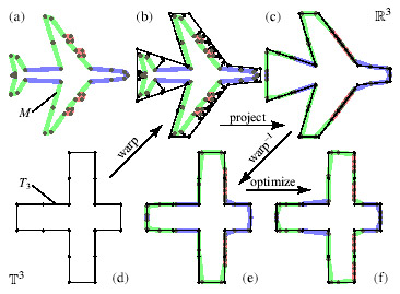 図7:メッシュ(a)の頂点に3Dテクスチャ座標値を設定する私たちの技術を2Dにして考えた場合:
私たちは、最初にメッシュ(b)に近いポリキューブ(d)で包みます。
次に、私たちは頂点を包んだポリキューブ表面(c)に法線方向で投影し、結果を戻すように包んで(e)、最後にテクスチャ座標値を最適化します。
上の列のメッシュはR3上にあり、下の列にあるメッシュはT3にあります。
図7:メッシュ(a)の頂点に3Dテクスチャ座標値を設定する私たちの技術を2Dにして考えた場合:
私たちは、最初にメッシュ(b)に近いポリキューブ(d)で包みます。
次に、私たちは頂点を包んだポリキューブ表面(c)に法線方向で投影し、結果を戻すように包んで(e)、最後にテクスチャ座標値を最適化します。
上の列のメッシュはR3上にあり、下の列にあるメッシュはT3にあります。
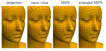 図8:異なる技術を使用して射影(左)によって作成した、初期のパラメター化の最適化:
拡張MIPS方法(右)がうまく角度とエリアの変形の平衡を保っている一方、
中間値座標およびMIPS方法(中間)は巨視的なエリアのひずみを犠牲にして等角の地図を作る傾向があります。
図8:異なる技術を使用して射影(左)によって作成した、初期のパラメター化の最適化:
拡張MIPS方法(右)がうまく角度とエリアの変形の平衡を保っている一方、
中間値座標およびMIPS方法(中間)は巨視的なエリアのひずみを犠牲にして等角の地図を作る傾向があります。
6.2 参照表の構築 Construction of the look-up table
一旦ポリキューブが指定されたら、T3LUTの構築は単純です。 ポリキューブの頂点を含んでいるセルごとについては、T3LUTの中の対応するエントリーeへの基礎的な場合であるe.Cおよび回転e.Rを割り当てます。 それぞれ、その頂点へかかわる8つの立方体の配置によって完全に決定されます。 また、私たちは、2多様体ポリキューブ表面の頂点の回転で生じることができる、63の可能な配置をあらかじめ計算することができます。
Once the polycube has been specified, the construction of T3LUT is simple. For each cell that contains a vertex of the polycube we assign the basic case e.C and a rotation e.R to the corresponding entry e in T3LUT . Both are fully determined by the arrangement of the eight cubes incident to that vertex and we can easily precompute the 63 possible configurations that can occur around the vertices of a two-manifold polycube surface.
さらにすべての空でないのセル用のグローバルオフセットe.O、つまりT2の内部のテクスチャパッチの全体的名詰め込みの定義を割り当てます この単純なつめこみには、非常に単純な発見的取り扱いをします。 例えば、私たちは、左から右まで、および上から下までT2を走査して、第1の利用可能な場所にパッチを設定することを繰り返します(図9および12を参照)。
We further assign the global offset e.O for all non-empty cells, thus defining the global packing of the texture patches inside T2. Even very simple heuristics deal well with this simple packing. For example, we can iteratively assign patches to the first available place, scanning T2 from left to right and from top to bottom (see Figures 9 and 12).
もちろん、私たちは、2N×2MテクスチャスペースT2全体をカバーすることは保証できません。しかし、これは小さな問題です。 多数のモデルのためにテクスチャメモリの中でテクスチャを持ち続ける必要がある場合は常に、 テクスチャスペースの小さな小片だけが未使用になるように、それらを同じグローバルテクスチャマップの中に詰めることができます。
Of course, we cannot guarantee to cover the entire 2N×2M texture space T2, but this is a minor problem. Whenever we need to keep textures for multiple models in the texture memory, they can be packed in the same global texture map so that only a small fraction of texture space will be left unused in the end.
7 実験結果 Experimental Results
ポリキューブマップの可能性をテストするために、私たちはセクション6に記述された方法でいくつかの例(図10および12を参照)を実装しました。 テクスチャマップT2のテクセルは規則的なパターンか最高解像度のメッシュのシェーディングによって塗られています[Cignoni et al. 1999]。 我々の方法は閉じた表面に制限されていないことに注意してください。 実際問題、Lauranaのモデルは底が開いていまて、ポリキューブ表面が底で開いている限り、私たちは今までどおりポリキューブマップを使用することができます(図11を参照)。
To test the potential of PolyCube-Maps, we produced a few examples (see Figures 10 and 12) with the method described in Section 6. The texel values of the texture map T2 have been filled using either a regular pattern or the shading of the mesh at highest resolution as in [Cignoni et al. 1999]. Note that our method is not limited to closed surfaces. In fact, the Laurana model is open at the bottom and we can still use PolyCube-Maps as long as the polycube surface is open at the bottom, too (see Figure 11).
テーブル1は、根本的なポリキューブなパラメター化の質をドキュメント化するいくつかのひずみの測定をリストし、[Gu et al. 2002]および[Praun and Hoppe 2003]の結果とそれを比較します。 パラメター化領域として、水平な領域(Guらは正方形を使用した)や単純な球形(PraunとHoppeは観念的な固体を使用した)の代わりにポリキューブ表面を使用することが、全体的なひずみを縮小することを助けるのが理解できるかもしれません。 ポリキューブがメッシュに似た形を持つので、これは驚くべきことではありません。
Table 1 lists several distortion measures that document the quality of the underlying poly-cubic parameterizations and compares it with the results of Gu et al. [2002] and Praun and Hoppe [2003]. It can be seen that using a polycube surface as parameterization domain instead of a flat domain (Gu et al. use a square) or simple spherical shapes (Praun and Hoppe use platonic solids) helps to reduce the overall distortion. This is not surprising because the polycube has a shape similar to that of the mesh.
メッシュ独立性Mesh independence.
さらに、私たちは、図12の中に見られるように、与えられたメッシュのいくつかの簡略版に対して同じのポリキューブマップを適用することができます。 私たちの方法の重要な特性は、元ののメッシュの単純化に際してポリキューブマップを考慮に入れる必要がないことで、また、その逆も成り立ちます。 言いかえれば、テクスチャパラメータ化のために、極わずかな単純化操作(例えばエッジの崩壊)も禁止する必要がありません。また、一方では、テクスチャT2の定義および参照テーブルT3LUTは、両方とも単純化プロセスと無関係にあります。
We can also apply a single PolyCube-Map to several simplified versions of a given mesh as shown in Figure 12. A key property of our method is that the simplification of the original mesh does not have to take the PolyCube-Map into account and vice versa. In other words, none of the atomic simpli-fication operations (e.g. edge collapse) has to be forbidden because of the texture parameterization, and on the other hand, the definition of the texture T2 and the look-up table T3LUT are both independent of the simplification process.
そのような簡略化の話とは別に、すべての頂点に3Dテクスチャ位置が適切に定義されていれば、多重詳細度モデルや再メッシュされたもの(四辺形のものさえ)を含む、元のモデルと一般的な形を共有する他のモデルにも同じポリキューブマップを張ることができます(図3を参照)。 私たちの例において、私たちは単純化されたモデルの各頂点に、それを含む3角形の各頂点のテクスチャ座標値の線形補間によって次には定義される、元のモデルの表面に(法線ベクトル方向で)一番近い3Dテクスチャ座標値を割り当てました
Apart from such simplified versions, the same PolyCube-Map would also work with other models that share the general shape of the original one, including multi-resolution structures and remeshes (even quadrilateral ones), as long as an appropriate 3D texture position is defined for every vertex (see Figure 3). In our example we assigned to each vertex of the simplified meshes the 3D texture position of the closest point (in the normal direction) on the surface of the original model which in turn is defined by linear interpolation of the texture coordinates at the corners of the containing triangle.
描画効率Rendering performance.
ポリキューブマップを備えたテクスチャ・マッピングは、要求される長いフラグメントシェーダのためにフィルレート限界を下げます。 まだ、ほとんど全画面を覆ったときでさえ、私たちは、ミップマップありのバイリニア補間なしのときに 30 fps以下に、両方行ったときでさえ 10 fps を下回るフレームレートを経験しませんでした。 テストは2.4 Ghzを備えたペンティアム4上で、nVIDIA GeForce FX 5600およびATI Radeon 9800 Proで実行されました。
Texture mapping with PolyCube-Maps can slow down a fill-limited application because of the longer fragment shader required. Still we never experienced the frame rate to drop below 30 fps with mip-mapping and without bilinear interpolation or 10 fps with both turned on, even when most of the screen was covered. Tests were performed with an nVIDIA GeForce FX 5600 and an ATI Radeon 9800 Pro on a Pentium 4 with 2.4 Ghz.
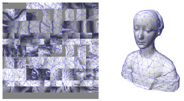 図9:テクスチャパッチの詰め込みはほとんど完全です。また、三角形が多数のスクエアレットを横切って広がっていることが見れるでしょう。
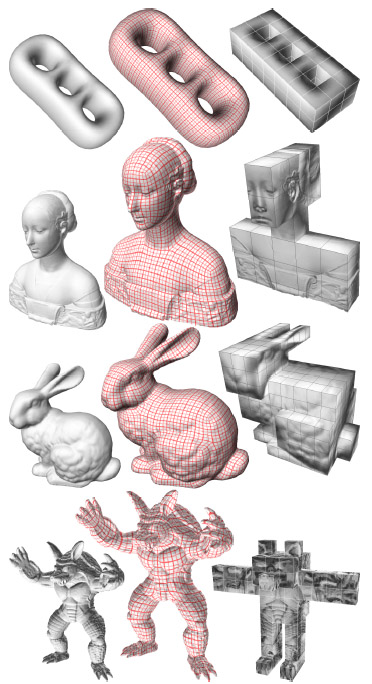 図10:ポリキューブのパラメター化を備えたモデルの例:元のモデル(左), 規則的なグリッドをポリキューブのテクスチャとして使った場合(中間)、ポリキューブの表面を覆うメッシュのパラメター化の濃淡(右)。
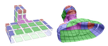 図11:私たちの方法は、さらにポリキューブがこの特徴を捕らえて、また開いている限り、開いたメッシュを扱うことを可能にします。
ポリキューブのフェイスレットおよびメッシュ上の対応する部分は、セルの配置応じて色が付いています。
図11:私たちの方法は、さらにポリキューブがこの特徴を捕らえて、また開いている限り、開いたメッシュを扱うことを可能にします。
ポリキューブのフェイスレットおよびメッシュ上の対応する部分は、セルの配置応じて色が付いています。
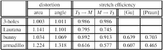 テーブル1:図10からのポリキューブのパラメター化φのひずみ。
エリアと角度のひずみは値σ1σ2+1/(σ1σ2)そしてσ1/σ2+σ2/σ1の統合および正規化されて測定されます。ここで、σ1とσ2はヤコビアンのマトリックスJφ(参照[Degener et al. 2003]また詳細には[Floater and Hormann 2004])の特異値です。
伸張効率は[Praun and Hoppe 2003]行われた手法で計算されます。
すべての手段については、最適の値が1です。
テーブル1:図10からのポリキューブのパラメター化φのひずみ。
エリアと角度のひずみは値σ1σ2+1/(σ1σ2)そしてσ1/σ2+σ2/σ1の統合および正規化されて測定されます。ここで、σ1とσ2はヤコビアンのマトリックスJφ(参照[Degener et al. 2003]また詳細には[Floater and Hormann 2004])の特異値です。
伸張効率は[Praun and Hoppe 2003]行われた手法で計算されます。
すべての手段については、最適の値が1です。
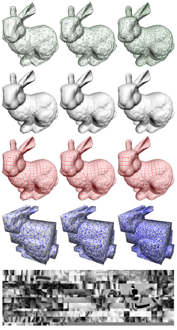 図12:同じポリキューブマップを異なる簡略化版モデルに適応(トップ)。規則的なパターンか与えられたメッシュのシェーディング(中間)。
対応するポリキューブのパラメター化およびテクスチャT2は一番下にあります。
図12:同じポリキューブマップを異なる簡略化版モデルに適応(トップ)。規則的なパターンか与えられたメッシュのシェーディング(中間)。
対応するポリキューブのパラメター化およびテクスチャT2は一番下にあります。
8 結果と検討 Conclusions and Discussion
ポリキューブマップは一般的な3Dメッシュに投影するテクスチャのための新しいメカニズムを提供します。 一旦適切なポリキューブが選ばれ、ポリキューブ表面に関する与えられたメッシュのポリキューブのパラメター化が計算されれば、それは似た形をした他のメッシュに色や他の情報をシームレスに使うことができます。
PolyCube-Maps provide a new mechanism for texture mapping general 3D meshes. Once an appropriate polycube is chosen and a poly-cubic parameterization of the given mesh over the polycube surface is computed, it can be used to seamlessly map colour or other signals onto that mesh and other models with a similar shape.
各スクエアレットが図表と考えられる場合、ポリキューブマップは、1つだけ重要な違いがある多重図表方法と見なすことができます。 もしポリキューブマップをメッシュ表面に全体に定義される関数と見せば、最終の2Dテクスチャ座標は、図表境界で不連続ですが、根本的な3Dテクスチャ座標が連続的なので、これらの不連続は目に見えません。 また、それらが、ユーザから見えないフラグメント単位で扱われるので、ポリキューブマップは、ミップマップを含む、導入部で議論された継ぎ目なしのマッピングという長所をすべて持ちます。 さらに、ポリキューブマップはメッシュとは独立しており、また、テクスチャパッチの詰め込みは、長方形という単純な形のゆえ自明であり、ほとんどテクスチャ容量を浪費しません。
If each squarelet is considered a chart, then a PolyCube-Map can be seen as a multi-chart method, but with one important difference. Although the final 2D texture coordinates, if seen as a function that is defined over the mesh surface, are discontinuous at the chart boundaries, these discontinuities are not visible because the underlying 3D texture coordinates are continuous. And since they are dealt with on a per-fragment basis that is hidden from the user, PolyCube-Maps have all the advantages of a seamless mapping that were discussed in the introduction, including mip-mapping. Moreover, PolyCube-Maps are mesh independent and the packing of texture patches is trivial because of their simple rectangular shape and it causes almost no wasted texture space.
8.1 ポリキューブマップの限界 Limits of PolyCube-Maps
明らかに、ポリキューブマップは、さらにそれらの適用可能性の範囲に限界を行っています。 メッシュの幾何かトポロジーが複雑すぎるか、非常に異なる規模で特徴を持っている場合、適切なポリキューブは、非常に多くの立方体になり、対応するT3LUTのサイズがすぐにテクスチャメモリを超えるでしょう。 極端な例は幹、枝および葉を備えた木のモデルになるでしょう。
Obviously, PolyCube-Maps also have limits in the scope of their applicability. If the geometry or topology of a mesh is too complex or has features at very different scales, then an appropriate polycube would consist of so many cubes that the size of the corresponding T3LUT would soon exceed the texture memory. An extreme example would be a model of a tree with trunk, branches, and leaves.
セクション7のうち、私たちは、同じオブジェクトの異なる表現をマッピングするテクスチャのために単一のポリキューブマップを使用することができることを紹介しました。 しかしながら、そのような表現がポリキューブマップが構築された元のメッシュにあまりに反する場合、生成されたフラグメントのテクスチャ座標値は、偶然、目に見えるレンダリング結果として残こる空のセルに落ちることがあります。
In Section 7 we showed that a single PolyCube-Map can be used for texture mapping different representations of the same object. However, if such a representation deviates too much from the original mesh for which the PolyCube-Map was constructed, then it can happen that the texture position of a produced fragment falls in an empty cell, which results in a visible rendering artefact.
8.2 幾何学的イメージ Geometry images
ポリキューブマップは、テクスチャ・マッピングのために設計された特別のタイプのパラメター化を表現します。しかし、さらに、それは再メッシュ化や目的を格納するために使用でき、幾何学イメージの変数になります[Gu et al. 2002]。 T2の中の個々の最終テクセルは、(r、g、b)チャンネルへ座標(x、y、z)を写像することにより、メッシュのサンプルを格納できます。 したがって、テクスチャT2とT3LUTの組は、オリジナルのモデルの1組の完全な表現と見なすことができます。
PolyCube-Maps represent a special type of parameterization that has been designed for texture mapping, but it can also be used for remeshing and storing purposes, becoming a variant of geometry images [Gu et al. 2002]. Each final texel in T2 can be used to store a sample of the mesh by mapping the coordinates (x,y,z) to the (r,g,b) channels. The pair of textures T2 and T3LUT can then be seen as a stand-alone representation of the original model.
特に、T2の中の各スクエアレットは、自明に定義された接続性(4の隣接したテクセルの各グループは四角形を形成する)を備えた符号化された表面の一部分を符号化するでしょう。 その後、T3LUTに格納される情報は、単一の首尾一貫したメッシュの中への一部分を復号するのに使われるでしょう。 近隣の一部分の側は同数の点を持つので、これは容易でしょう。
In particular, each squarelet in T2 would encode a subpart of the encoded surface with a trivially defined connectivity (each group of four adjacent texels forms a quad). The information that is stored in T3LUT would then be used to zipper the subparts into a single coherent mesh. This would be easy because the sides of neighbouring subparts have the same number of points.
8.3 将来の展望 Future work
拡張。 GPUのプログラム化が進めば、フラグメントプログラム命令の数はそれほど問題でなくなり、私たちが現在のインプリメンテーションでやり残したセルの場合を含むことは可能でしょう。 どんな2多様体ポリキューブ表面も3Dテクスチャ領域T3として使用することができるでしょう。 別の有用な拡張は、3D参照テーブルT3LUTへのあまりにも多い追加のアクセスを要求しないように注意する、テクスチャ空間T3の細分化のための(例えばoctreesを備えた)ある階層的アプローチでしょう。
Extensions. As soon as the GPU programmability has advanced so that the number of fragment program instructions is less critical, it will be possible to include the cell cases that we left out of the current implementation. Any two-manifold polycube surface can then be used as 3D texture domain T3. Another useful extension would be some hierarchical approach (e.g. with octrees) for the subdivision of the texture space T3, taking care not to require too many additional accesses to the 3D look-up table T3LUT .
タイルが張られたテクスチャ。 ポリキューブマップは、新式のテクスチャのタイル張り方法の可能性を持っています。 各セル配置については、私たちは一致する境界を備えた2Dテクスチャパッチを作成し格納することができました。 また、および3D参照テーブルは一種の2多様体Wangタイル[Cohen et al. 2003]中のポリキューブ表面上に継ぎ目のないマップとして使われるでしょう。 この結果はラップテクスチャ [Praun et al. 2000]と似たものになるでしょう。 しかし再サンプリングされたテクスチャマップを使用したり、アルファ合成を使って三角形を何度も描画する必要はありません。
Tiled textures. PolyCube-Maps have the potential for a new type of tiled textures. For each cell configuration we could create and store 2D texture patches with matching boundaries, and the 3D look-up table would then be used to seamlessly map them onto the polycube surface in a sort of two-manifold Wang Tiles scheme [Cohen et al. 2003]. The result would be similar to lapped textures [Praun et al. 2000] b ut without the need to use a resampled texture atlas or to render triangles multiple times with alpha blending.
自動パラメター化。 私たちは、この仕事が平らな定義域あるいは単純な複雑さを持つものの代わりに、ポリキューブ表面でメッシュをパラメター化するという新しいカテゴリーの表面のパラメター化方法の道を開くと信じます。 最も興味深い部分はユーザの介在がないもしくは最小となるようにして適切なポリキューブを決定することでしょう。また、この新しい種類の領域に階層的な方法でそれらを促進すると同様に既存のパラメター化方法を適応させることも、有益な仕事となるでしょう。
Automatic parameterization. We believe that this work opens the way to a new category of surface parameterization methods that parameterize a mesh over a polycube surface instead of a flat domain or a coarse simplicial complex. The most challenging part will be to determine appropriate polycubes with minimal or no user intervention, but also adapting existing parameterization methods to this new kind of domain as well as speeding them up with hierarchical methods will be a worthwhile task.
謝辞 Acknowledgements
この仕事は、プロジェクトViHAP3D(EU IST-2001-32641)、MACROGeo(FIRB-MIUR RBAU01MZJ5)に、およびドイツのForschungsgemeinschaft(DFG HO 2457/1-1)に支援されています。
This work was supported by the projects ViHAP3D (EU IST-2001-32641) and MACROGeo (FIRB-MIUR RBAU01MZJ5) and by the Deutsche Forschungsgemeinschaft (DFG HO 2457/1-1).
References
CARR, N. A., AND HART, J. C. 2002. Meshed atlases for real-time procedural solid texturing. ACM Transactions on Graphics 21, 2, 106・31.CIGNONI, P., MONTANI, C., ROCCHINI, C., SCOPIGNO, R., AND TARINI, M. 1999. Preserving attribute values on simplified meshes by resampling detail textures. The Visual Computer 15, 10, 519・39.
COHEN, J., OLANO, M., AND MANOCHA, D. 1998. Appearancepreserving simplification. In Proc. of ACM SIGGRAPH 98, 115・22.
COHEN, M. F., SHADE, J., HILLER, S., AND DEUSSEN, O. 2003. Wang Tiles for image and texture generation. ACM Transactions on Graphics 22, 3, 287・94.
DEGENER, P., MESETH, J., AND KLEIN, R. 2003. An adaptable surface parameterization method. In Proc. of the 12th International Meshing Roundtable, 201・13.
ECK, M., DEROSE, T., DUCHAMP, T., HOPPE, H., LOUNSBERY, M., AND STUETZLE, W. 1995. Multiresolution analysis of arbitrary meshes. In Proc. of ACM SIGGRAPH 95, 173・82.
FLOATER, M. S., AND HORMANN, K. 2004. Surface parameterization: a tutorial and survey. In Advances in Multiresolution for Geometric Modelling, N. A. Dodgson, M. S. Floater, and M. A. Sabin, Eds. Springer, 259・84.
FLOATER, M. S. 2003. Mean value coordinates. Computer Aided Geometric Design 20, 1, 19・7.
GRIMM, C. M. 2002. Simple manifolds for surface modeling and parameterization. In Proc. of Shape Modeling International 2002, 237・44.
GU, X., GORTLER, S. J., AND HOPPE, H. 2002. Geometry images. ACM Transactions on Graphics 21, 3, 355・61.
HORMANN, K., AND GREINER, G. 2000. MIPS: An efficient global parametrization method. In Curve and Surface Design: Saint-Malo 1999, P.-J. Laurent, P. Sablonni`ere, and L. L. Schumaker, Eds. Vanderbilt University Press, 153・62.
KHODAKOVSKY, A., LITKE, N., AND SCHR ィODER, P. 2003. Globally smooth parameterizations with low distortion. ACM Transactions on Graphics 22, 3, 350・57.
LEE, A. W. F., SWELDENS, W., SCHR ィODER, P., COWSAR, L., AND DOBKIN, D. 1998. MAPS: multiresolution adaptive parameterization of surfaces. In Proc. of ACM SIGGRAPH 98, 95・04.
LエEVY, B., PETITJEAN, S., RAY, N., AND MAILLOT, J. 2002. Least squares conformal maps for automatic texture atlas generation. ACM Transactions on Graphics 21, 3, 362・71.
MAILLOT, J., YAHIA, H., AND VERROUST, A. 1993. Interactive texture mapping. In Proc. of ACM SIGGRAPH 93, 27・4.
PIPONI, D., AND BORSHUKOV, G. 2000. Seamless texture mapping of subdivision surfaces by model pelting and texture blending. In Proc. of ACM SIGGRAPH 2000, 471・78.
PRAUN, E., AND HOPPE, H. 2003. Spherical parametrization and remeshing. ACM Transactions on Graphics 22, 3, 340・49.
PRAUN, E., FINKELSTEIN, A., AND HOPPE, H. 2000. Lapped textures. In Proc. of ACM SIGGRAPH 2000, 465・70.
SANDER, P., WOOD, Z., GORTLER, S. J., SNYDER, J., AND HOPPE, H. 2003. Multi-chart geometry images. In Proc. of the Symposium on Geometry Processing 2003, 146・55.
SCHNEIDER, J., AND WESTERMANN, R. 2003. Compression domain volume rendering. In Proc. of Visualization 2003, 293・00.
SHEFFER, A., AND HART, J. C. 2002. Seamster: inconspicuous lowdistortion texture seam layout. In Proc. of Visualization 2002, 291・98.
SORKINE, O., COHEN-OR, D., GOLDENTHAL, R., AND LISCHINSKI, D. 2002. Bounded-distortion piecewise mesh parameterization. In Proc. of Visualization 2002, 355・62.